Installation can be simple or complex depending on what you want to interface.
WARNINGS
1/ Always power down the PLEV (electric scooter, electric bike …) before starting installation, by either :
- unplugging the battery,
- or switch off with the main power button (the whole plev must be unpowered),
- or switch off the BMS
2/ Empty the capacitors of the motor controller. To do that, power on the PLEV one last time after the main power is down. The display must power on briefly and power down. The capacitors are now empty.
3/ Never touch the SmartDisplay PCB with your finger when it is powered, or just after power it off (wait 5 min for the capacitor to leak the remaning voltage).
4/ Always install your PLEV in a place where wheels can spin freely during installation.
5/ Do not use more than 500mA on the VB output. If a DC/DC regulator (for lights for example) is connected to the SmartDisplay or Controller, do not use if if it is allows more than 5A ouput.
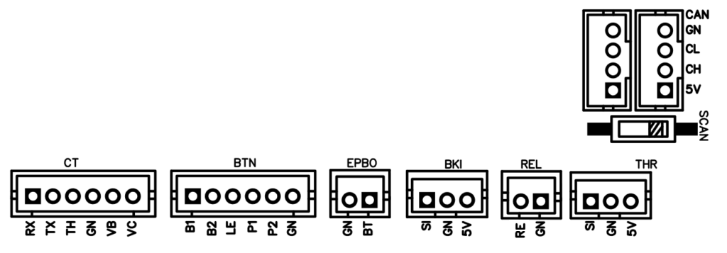
SmartDisplay connectors and switches description

CT connector : for controller interface.
- RX : data received from controller with UART interface (often named TX on the controller side)
- TX : data sent to controller with UART interface (often named RX on the controller side)
- TH : throttle signal
- GN : ground signal
- VB : voltage sent to controller when display is powered on
- VC : main voltage received by controller (12V to 100V)
BTN connector : for buttons interface
- B1 : button 1 signal (left button)
- B2 : button 2 signal (middle button)
- LE : led 3.3V signal
- P1 : power button (right button)
- P2 : power button (right button)
- GN : ground
EPBO connector : for external power button connector
- GN : ground
- BT : right/power button feedback
BKI connector : for brake connector
- SI : hall or 5V signal input for SmartDisplay
- GN : ground
- 5V : 5V generated by smartDisplay to power on the hall sensor or create a voltage loop on SI for digital brake (ON/OFF switch on the lever)
REL : for relay output interface
- RE (or SI on old PCB) : relay signal
- GN : ground
THR connector : for throttle interface
- SI : hall signal input for SmartDisplay
- GN : ground
- 5V : 5V generated by smartDisplay to power on the hall sensor
CAN connector : for VESC and expansion boards interface
- GN : ground. DO NOT CABLE TO VESC (you’ll create ground loop)
- CL : CAN low signal
- CH : CAN high signal
- 5V : used to power expansion board. DO NOT CABLE TO VESC
SCAN switch : for CAN bus terminaison
- position ‘1’ : terminaison is not active
- position ‘ON’ : 120ohm terminaison is enabled
Wiring
Buttons
The remote buttons require an additionnal cable for the 3 buttons interface. It allows you to control the SmartDisplay. Buttons action is configurable through TFT menu, bluetooth or wifi.
Brake
It is compatible with any 2 wires (digital on/off brake) or 3 wires (hall sensor brake) lever sensors.
Throttle
It is compatible with any 3 wires throttle.
Expansion boards
You can add as many expansion boards. They are chained by a CAN bus.
Controller
The controller must be the last part you plug in on the SmartDisplay PCB.
It requires a single cable going from the SmartDisplay to the motor controller.
With VESC, you can either use the same cable, or use the CAN controller can (see wiring diagrams).
Cables
coming soon
